
I haven’t installed a set of these, I just figured out how to build the harness for johan13 to get them up and running. I actually don’t even have a 2019, I have a 2017, but I ordered them a week ago to install on my 2017 since they will fit.Hi
The dealership I purchased the boards from told me they would add the code to my system. I would prefer to get the correct boards for my vehicle. I've got no problem returning everything to them and starting over.
As for the codes, The dealership told me they would add the code to my vehicle so it's consider a dealership added option.
Just for a quick check I was able to build the same vehicle on the RAM website with the power running boards as an option so I would think they could add that feature code.
How are your running boards installed on your 2019 2500 RAM? Did you have bolts, or hangers (like I've seen the AMP installs go)?
Ram Heavy Duty Forum
You are using an out of date browser. It may not display this or other websites correctly.
You should upgrade or use an alternative browser.
You should upgrade or use an alternative browser.
mopar Power Deployable Running Boards
- Thread starter johanh13
- Start date
johanh13
Active Member
- Joined
- Aug 10, 2019
- Messages
- 191
- Reaction score
- 115
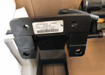
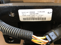
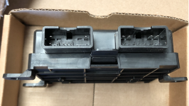
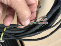
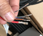
I was also sold this kit, but the boards are so different, there will be no way to properly mount them. After thoroughly looking everything over, I returned the kit. I attached a bunch of photos, maybe its possible to determine if the wiring kit would work on the 2500/3500? I was unable to ascertain where any of the wire ends would go..... Jimmy07, what do you think, will this wiring work on a 2500?Hello,
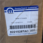
This is a wonderful thread. Sounds like @Jimmy07 , @johanh13 have been successful installing the Mopar Power Running boards on their 2019 2500's. I just picked up the parts from the dealership and was told this was the kit I needed. The part number is 82215287AC. I was told by the dealership this kit would fit my new 2020 2500 Laramie Crew Cab. The kit came with two power running boards, the BCM, 1 wiring hiring harness to connect the two boards and power to the BCM and one to connect the BCM to the CAN bus and ground. The instructions seem pretty simple, however the instructions show that there should be bolts on the vehicle to mount the boards and there are no bolts. I'm wondering if others ran into this and if there is a kit for the bolts.
BTW - I needed the truck with specific options and could not wait to order one, so I'm hoping I can add these since I got most of what I needed. With the COVID shutdown of the assembly plants the current supply is very limited.
Also in all of my searching on that part number it only appears associated with a RAM 1500 so now I'm wondering if I this will work at all.
Here are the sub parts on the kit in case anyone is interested
Power side step LT (Crew) - 68275813AB
Power side step RT (Crew) - 68275812AB
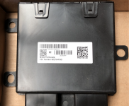
BCM - 68275941AD
Thanks for any help!
Attachments
-
 Screen Shot 2020-07-11 at 12.04.20 AM.png3.1 MB · Views: 89
 -
 Screen Shot 2020-07-11 at 12.04.29 AM.png3.5 MB · Views: 85
 -
 Screen Shot 2020-07-11 at 12.04.49 AM.png2.4 MB · Views: 83
 -
 Screen Shot 2020-07-11 at 12.05.12 AM.png3.4 MB · Views: 83
 -
 Screen Shot 2020-07-11 at 12.05.20 AM.png2.5 MB · Views: 79
 -
 Screen Shot 2020-07-11 at 12.05.29 AM.png3.6 MB · Views: 78
 -
 Screen Shot 2020-07-11 at 12.05.38 AM.png3.6 MB · Views: 81
 -
 Screen Shot 2020-07-11 at 12.05.52 AM.png4 MB · Views: 81
 -
 Screen Shot 2020-07-11 at 12.06.02 AM.png3.9 MB · Views: 86
 -
 Screen Shot 2020-07-11 at 12.06.12 AM.png4.3 MB · Views: 92
johanh13
Active Member
- Joined
- Aug 10, 2019
- Messages
- 191
- Reaction score
- 115
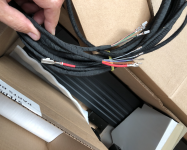
here are four more photos (could only attach ten)I was also sold this kit, but the boards are so different, there will be no way to properly mount them. After thoroughly looking everything over, I returned the kit. I attached a bunch of photos, maybe its possible to determine if the wiring kit would work on the 2500/3500? I was unable to ascertain where any of the wire ends would go..... Jimmy07, what do you think, will this wiring work on a 2500?
Attachments
The harness will work with all the 2500 parts, except for the size of the terminal that plugs into the PDC connector, but no big deal. It looks like mopar built the harness to start working from the outside in, instead of the way I’d prefer working from inside out. I would just return the whole kit for the full refund though.I was also sold this kit, but the boards are so different, there will be no way to properly mount them. After thoroughly looking everything over, I returned the kit. I attached a bunch of photos, maybe its possible to determine if the wiring kit would work on the 2500/3500? I was unable to ascertain where any of the wire ends would go..... Jimmy07, what do you think, will this wiring work on a 2500?
@mtnscott, if you end up getting the correct boards and module, I can build the harness for you, since I ordered extra parts when I ordered for mine.
johanh13
Active Member
- Joined
- Aug 10, 2019
- Messages
- 191
- Reaction score
- 115
A few other notes: the 1500 has the module under the steering wheel shaft, so the wires would not be long enough to put the module in the stock location for a 2500. Also, where is the gray connector, the can-bus wires, and the ground wire?The harness will work with all the 2500 parts, except for the size of the terminal that plugs into the PDC connector, but no big deal. It looks like mopar built the harness to start working from the outside in, instead of the way I’d prefer working from inside out. I would just return the whole kit for the full refund though.
@mtnscott, if you end up getting the correct boards and module, I can build the harness for you, since I ordered extra parts when I ordered for mine.
The harness will work with all the 2500 parts, except for the size of the terminal that plugs into the PDC connector, but no big deal. It looks like mopar built the harness to start working from the outside in, instead of the way I’d prefer working from inside out. I would just return the whole kit for the full refund though.
@mtnscott, if you end up getting the correct boards and module, I can build the harness for you, since I ordered extra parts when I ordered for mine.
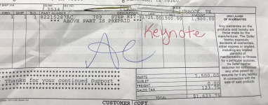
I took back the kit and ordered the following parts -
1 68361654AA - Power running board Right
1 68361655AA - Power running board Left
1 68367399AE - Controller Module
These were also on the worksheet with the boards but not entirely sure if I needed them. Dealer told me I can return what I don't use
8 6511062AA - NUT / RIVET
8 6507610AA - BOLT - HEX HEAD
8 6102165AA - SCREW
I also ordered the wiring harness from the kit, but as you indicated it won't work as the controller unit needs to be mounted in a different location. So I would like to discuss with you on your offer for making a wiring harness.
I can call the dealership Monday and cancel the order of the harnesses.
A few other notes: the 1500 has the module under the steering wheel shaft, so the wires would not be long enough to put the module in the stock location for a 2500. Also, where is the gray connector, the can-bus wires, and the ground wire?
Johanh13, how did you mount the running boards on your truck? Are there factory holes that we install the rivet nuts into, or did you use something else?
johanh13
Active Member
- Joined
- Aug 10, 2019
- Messages
- 191
- Reaction score
- 115
Yes, I used the extra parts (did not double check the numbers); rivnuts/bolts. The holes are already there...Johanh13, how did you mount the running boards on your truck? Are there factory holes that we install the rivet nuts into, or did you use something else?
The controller doesn’t “need” to be mounted in any certain spot. All the connectors and circuits are exactly the same between the DT and HD truck power steps. Since you were able to order the harness separately, I would just use it. Just follow the directions for the wiring portion of the kit instructions, and wherever the connectors end up for the module location, just find a clever way to mount it in that spot.I took back the kit and ordered the following parts -
1 68361654AA - Power running board Right
1 68361655AA - Power running board Left
1 68367399AE - Controller Module
These were also on the worksheet with the boards but not entirely sure if I needed them. Dealer told me I can return what I don't use
8 6511062AA - NUT / RIVET
8 6507610AA - BOLT - HEX HEAD
8 6102165AA - SCREW
I also ordered the wiring harness from the kit, but as you indicated it won't work as the controller unit needs to be mounted in a different location. So I would like to discuss with you on your offer for making a wiring harness.
I can call the dealership Monday and cancel the order of the harnesses.
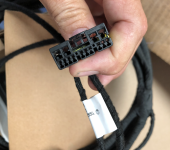
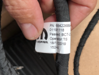
The Grey Connector is separate in the kit as once you feed the wires thru the firewall you need to insert the wires into the grey connector. There is another wiring harness 68422689AB - that connects the ground and canbus wires.A few other notes: the 1500 has the module under the steering wheel shaft, so the wires would not be long enough to put the module in the stock location for a 2500. Also, where is the gray connector, the can-bus wires, and the ground wire?


There’s two different part numbers for each right and left power step for the HDs.Does anyone have the part number for the boards for the Mega cab? I'm assuming the control module will be the same... And @Jimmy07, I would be interested in having you make me a wiring harness if you're interested in making me a set.
68361655AA left
68361654AA right
Those are the ones used in this thread on a crew cab.
68361657AA left
68361656AA right
I can only *ASSUME* that these would be for the mega cab. This is the VIN of a mega cab with power steps- 3C6UR5TL7KG727183. I would have the dealership parts department use that VIN to make sure those are the correct part numbers. The module is the same for all HDs. I’ll send you a PM about a harness.
The controller doesn’t “need” to be mounted in any certain spot. All the connectors and circuits are exactly the same between the DT and HD truck power steps. Since you were able to order the harness separately, I would just use it. Just follow the directions for the wiring portion of the kit instructions, and wherever the connectors end up for the module location, just find a clever way to mount it in that spot.
Hi @Jimmy07. You mentioned you had extra parts from building the harness for @johanh13. Do you happen to have the part for the grey connector? The dealership was unable to track down the sub part of the kit that has that connector. They even reached out to Chrysler but were unable to identify it. I will need it to complete my installation so if you can offer any guidance I would greatly appreciate it.The harness will work with all the 2500 parts, except for the size of the terminal that plugs into the PDC connector, but no big deal. It looks like mopar built the harness to start working from the outside in, instead of the way I’d prefer working from inside out. I would just return the whole kit for the full refund though.
@mtnscott, if you end up getting the correct boards and module, I can build the harness for you, since I ordered extra parts when I ordered for mine.
I didn’t build the harness for johanh13, but I did build an extra harness. I don’t have any spare parts either. The part number of the connector you need is Yazaki 7283-8398-40Hi @Jimmy07. You mentioned you had extra parts from building the harness for @johanh13. Do you happen to have the part for the grey connector? The dealership was unable to track down the sub part of the kit that has that connector. They even reached out to Chrysler but were unable to identify it. I will need it to complete my installation so if you can offer any guidance I would greatly appreciate it.
johanh13
Active Member
- Joined
- Aug 10, 2019
- Messages
- 191
- Reaction score
- 115
I have some extra connectors... do you just need the gray one? I have the bare-naked connectors....Hi @Jimmy07. You mentioned you had extra parts from building the harness for @johanh13. Do you happen to have the part for the grey connector? The dealership was unable to track down the sub part of the kit that has that connector. They even reached out to Chrysler but were unable to identify it. I will need it to complete my installation so if you can offer any guidance I would greatly appreciate it.
Attachments
I just got my parts and have several questions
Does anyone know the torque settings for the fusebox power connector and the running board bolts that go into the rivet nuts.
Which STAR CAN IHS block does the connector go into that connects with the PSSM? There are two as shown in @johanh13 post.
What fuse block terminal does the red power wire connect to? The fuse is F15 and does anyone know what the size of the fuse is?
Can you also share which STAR CAN IHS block you used for the power running boards CAN connection? I was told that if you install on the left block (in your picture) that they need to be adjacent to other connections due to termination requirements.
Does anyone know the torque settings for the fusebox power connector and the running board bolts that go into the rivet nuts.
Which STAR CAN IHS block does the connector go into that connects with the PSSM? There are two as shown in @johanh13 post.
What fuse block terminal does the red power wire connect to? The fuse is F15 and does anyone know what the size of the fuse is?
@johanh13 Can you share how you connected the red wire to the fuse F15 location in the PDC? What connector and location on the PDC does the supply wire for the Power Board Controller module go?Ok, so I got the correct pin for the fuse box connection yesterday and put it in. Now just waiting for the bluetooth adapter so I can do the programming for the screen menu.... everything works great even as is!
Can you also share which STAR CAN IHS block you used for the power running boards CAN connection? I was told that if you install on the left block (in your picture) that they need to be adjacent to other connections due to termination requirements.
johanh13
Active Member
- Joined
- Aug 10, 2019
- Messages
- 191
- Reaction score
- 115
I just got my parts and have several questions
Does anyone know the torque settings for the fusebox power connector and the running board bolts that go into the rivet nuts.
Which STAR CAN IHS block does the connector go into that connects with the PSSM? There are two as shown in @johanh13 post.
What fuse block terminal does the red power wire connect to? The fuse is F15 and does anyone know what the size of the fuse is?
@johanh13 Can you share how you connected the red wire to the fuse F15 location in the PDC? What connector and location on the PDC does the supply wire for the Power Board Controller module go?
Can you also share which STAR CAN IHS block you used for the power running boards CAN connection? I was told that if you install on the left block (in your picture) that they need to be adjacent to other connections due to termination requirements.
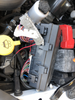
The fuse was already in my fuse panel, it is 30 amps. Attached is a photo of my wire installed and the existing wire pulled. I will see if I can find some more info for you on how to release the existing connector...

Last edited:
johanh13
Active Member
- Joined
- Aug 10, 2019
- Messages
- 191
- Reaction score
- 115
Here are the instructions @Jimmy07 sent me:The fuse was already in my fuse panel, it is 30 amps. Attached is a photo of my wire installed and the existing wire pulled. I will see if I can find some more info for you on how to release the existing connector...
View attachment 6604
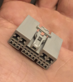
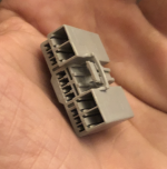
The terminal part number I come up with is Yazaki 7116-4120-02. It’s a 6.3mm wide socket, and is the largest of the 3 different sized sockets on the fuse box C6 connector. It’s total width is 7.5mm, which is just over one quarter inch wide.
To remove the existing wire, pry off the front face of the connector, part number 2-

Then stick a paper clip (possibly a jewelers screwdriver) in the front under the terminal and start prying to release the terminal. Insert the new wire before re-installing the face piece, as that locks all the terminals in place.
Last edited:
johanh13
Active Member
- Joined
- Aug 10, 2019
- Messages
- 191
- Reaction score
- 115
One more photo, shows more of an overall view, to show where the connector is...Here are the instructions @Jimmy07 sent me:
The terminal part number I come up with is Yazaki 7116-4120-02. It’s a 6.3mm wide socket, and is the largest of the 3 different sized sockets on the fuse box C6 connector. It’s total width is 7.5mm, which is just over one quarter inch wide.
To remove the existing wire, pry off the front face of the connector, part number 2-
View attachment 6605
Then stick a paper clip (possibly a jewelers screwdriver) in the front under the terminal and start prying to release the terminal. Insert the new wire before re-installing the face piece, as that locks all the terminals in place.
Attachments
Users who are viewing this thread
Total: 4 (members: 0, guests: 4)